Posts

Showing posts from October, 2019

Categories of Cutting Fluids in Machining

Image
Practically all cutt ing fluids presently in use fall into one of four categories: Straight oils Soluble oils Semisynthetic fluids Synthetic fluids S traight oils are non-emulsifiable and are used in machining operations in an undiluted form. They are composed of a base mineral or petroleum oil and often contains polar lubricants such as fats, vegetable oils and esters as well as extreme pressure additives such as Chlorine, Sulphur and Phosphorus. Straight oils provide the best lubrication and the poorest cooling characteristics among cutting fluids. S ynthetic Fluids contain no petroleum or mineral oil base and instead are formulated from alkaline inorganic and organic compounds along with additives for corrosion inhibition. They are generally used in a diluted form (usual concent ration = 3 to 10%). Synthetic fluids often provide the best cooling performance among all cutting fluids. S oluble Oil Fluids form an emulsion when mixed with water. The concentrate con

Cutting Fluid Effects in Machining

Image
The primary functions of cutting fluids in machining are : Lubricating the cutting process primarily at low cutting speeds Cooling the workpiece primarily at high cutting speeds Flushing chips away from the cutting zone Secondary functions include: Corossion protection of the machined surface enabling part handling by cooling the hot surface Process effects of using cutting fluids in machining include: Longer Tool Life Reduced Thermal Deformation of Workpiece Better Surface Finish (in some applications) Ease of Chip and Swarf handling 

Introduction to a cutting Fluid

Image
Cutting Fluid Cutting fluid is a type of  coolant  and  lubricant   designed  specifically for  metalworking  processes, such as  machining  and stamping. There are various kinds of cutting fluids, which include oils, oil-water  emulsions , pastes, gels, aerosols (mists), and air or other gases. They may be made from petroleum distillates,  animal fats ,  plant oils , water and air, or other raw ingredients. Depending on context and on which type of cutting fluid is being considered, it may be referred to as cutting fluid, cutting oil, cutting compound, coolant, or lubricant. Most metalworking and machining processes can benefit from the use of cutting fluid, depending on workpiece material. Common exceptions to this are  cast iron  and  brass , which may be machined dry (though this is not true of all brasses, and any machining of brass will likely benefit from the presence of a cutting fluid)

Introduction to Universal Grinding Machine

Image
Grinding: Grinding is a process carried out with a grinding wheel made up of abrasive grains for removing very fine quantities of material from the work piece surface. The required size of abrasive grains are thoroughly mixed with the bonding material and then pressed into a disc shaped of given diameter and thickness. Grinding process is used for two reasons (i)          Higher value of surface finish and accuracy that cannot be provided with the machining process. (ii)        Hard and brittle materials that cannot be machined or it is uneconomical to use machining   Grinding wheel A grinding wheel is made of abrasive grains held together by a bond. These grains cut like teeth when the wheel is revolved at high speed and is brought to bear against a work piece. The properties   of a wheel that determine how it acts are the ginding parameters including the kind and size of an abrasive matereial, how closely the grains are packed together and the type and amount of the b

Parts of Vertical Milling Machine

Image
Parts of Vertical Milling Machine The vertical knee mill is the most common milling machine found in machine shops today. Therefore it will be used as an example to describe the general parts of all mills. Head                The head (drive) is that part of the drive system that transforms electrical power from a motor to mechanical power in the spindle. The drive system also allows the machinist to change the speed of the spindle (RPM) and therefore the cutting tool. The quill moves vertically in the head and contains the spindle in which cutting tools are installed. Column                The column is the most important part which is mounted on the base and acts as a support and holding device for all the other parts of a milling machine. It acts as a support for table and all feed mechanisms. The column should be rigid enough to sustain all the forces produced due to the drilling action of the tool. The head and worktable are mounted with column. Work table It

Introduction to a Milling Machine

Image
Milling Machine A milling machine is a machine tool used for the shaping of metal and other solid material. Unlike a drill press, in which the workpiece is held stationary and the drill is moved vertically to penetrate the material, milling also involves movement of the workpiece against the rotating cutter, the latter which is able to cut on its flanks as well as its tip. Milling machines may be manually operated, mechanically automated, or digitally automated via computer numerical control (CNC).

Tool Holding Devices in Drill Machine

Image
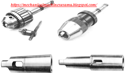
Tool-Holding Devices: Drill press spindle provides means of holding and driving cutting tool.End may be tapered or threaded for mounting drill chuck. Most common devices are used in Drill presses:       Drill chucks       Drill sleeves        Drill sockets Drill Chucks: Most common devices used for holding straight-shank cutting tools. Most contain three jaws that move simultaneously when outer sleeve turned. Hold straight shank of cutting tool securely. Two common types               Key   Keyless     Drill sleeves:                        Used to adapt cutting tool shank to machine spindle if taper on tool is smaller than tapered hole in spindle   Drill sockets:   Used when hole in spindle of drill press to small for taper shank of drill.  Used also as extension sockets.

Study of major parts of Upright Drill Machine

Image
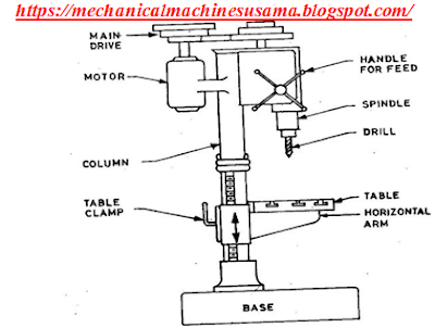
  Base:              The base is that part of a machine on which the column is mounted.   Column: The column is the most important part which is mounted on the base and acts as a support and holding device for all the other parts of an upright drilling machine. It acts as a support for table and all feed mechanisms. Table:           Table is the part on which the work piece is mounted. This is held up by fixing it to a column. A table can have rectangular geometry or circular in shape. Slots are provided on the table for holding the work piece very effectively. Three types of movements of the table are provided so as to achieve the centering very easily. The three movements incorporated in the table are   ·    Vertical adjustment ·    Radial adjustment around the column   ·   Circular adjustment about its own axis Head:   Drill head is the one which holds all the feed mechanisms and spindle drive motion. Drill head is mounted on the column. The head

Study of Operations Performs by Dril Machine

Image
Reaming: It is the operation of sizing and finishing a hole by means of a reamer having several cutting edges. Boring: It is the operation of enlarging a hole by means of an adjustable cutting tool with only one cutting edge. Counter Boring: It is the operation of enlarging the end of a hole cylindrical, in order to accommodate the screw head so that it does not protrude outside. Counter Sinking: It is the operation of a cone- shaped enlargement of the end of a hole. Spot Facing: It is the operation of smoothing and squaring the surface around a hole, as for the seat for a nut or the head to a cap screw. Tapping: It is the operation of forming internal threads by means of a tool called a tap.

Introduction to a Drill Machine

Image
Drill Machine: Drilling  is a process of making hole or enlarging a hole in an object by forcing a rotating tool called  Drill . The same  operation  can be accomplished in some other  machine  by holding the  drill  stationary and rotating the work. A   drill   is a   tool   fitted with a   cutting tool   attachment or driving tool attachment, usually a   drill bit   or   driver bit , used for   boring   holes in various materials or   fastening   various materials together with the use of fasteners. The attachment is gripped by a   chuck   at one end of the drill and rotated while pressed against the target material. The tip, and sometimes edges, of the cutting tool does the work of cutting into the target material. This may be slicing off thin shavings ( twist drills   or   auger bits ), grinding off small particles ( oil drilling ), crushing and removing pieces of the work piece, countersinking ,   counter boring , or other operations. Drill press:           A drill

Operations Performs on Lathe Machine

Image
Facing Facing is the process of removing metal from the end of a workpiece to produce a flat surface. Most often, the workpiece is cylindrical, but by using 4- jaw chuck we can face rectangular or odd-shaped work to form cubes and other non-cylindrical shapes. When a lathe cutting tool removes metal it applies considerable tangential (i.e. lateral or sideways) force to the workpiece. To safely perform a facing operation the end of the workpiece must be positioned close to the jaws of the chuck. The workpiece should not extend more than 2-3 times its diameter from the chuck jaws unless a steady rest is used to support the free end. Straight turning In this operation the work is held in the spindle and is rotated whole the tool is fed past the work piece in a direction parallel to the axis of rotation. The surface generated is a cylindrical surface. Taper Turning A taper may be defined as a uniform increase or decrease in diameter of a work piece measured along its length

Main parts of Lathe Machine

Image
          The Bed:                     The lathe bed is a mounting and aligning surface for the other machine components. Viewed from the operating position in front of the machine, the headstock is mounted on the left send of the bed and the tailstock on the right. The bed must be bolted to a base to provide a rigid and stable platform. 1        Head Stock:            The head stock is the part of the lathe which serves as a housing for the driving pulleys and back gears, provides bearing for the machine spindle and keeps the latter in alignment with the bed. It is a fixed part which will present on the left side of the lathe bed. Head stock will consists of a hollow spindle and drives unit like main spindle, feed reverse lever, live center cone pulley etc., The tapered bar with pointed or projected end is going to grip the work piece between two centers of lathe bed. 1     Carriage: The lathe carriage serves the purpose of supporting, guiding and feeding the tool ag

Introduction to a Lathe Machine

Image
A   lathe   is a   machine   tool which rotates the work piece on its axis to perform various operations such as cutting, sanding, knurling, drilling, or deformation, facing, turning, with tools that are applied to the work piece to create an object which has symmetry about an axis of rotation.or The lathe is a machine tool used in metal cutting operations called "turning." The work piece is rotated as tooling is applied to it to remove material.  Lathes can be manually operated or operated by computer numerical control (CNC). The lathe bed is a mounting and aligning surface for the other machine components. Viewed from the operating position in front of the machine, the headstock is mounted on the left end of the bed and the tailstock on the right. The bed must be bolted to a base to provide a rigid and stable platform.